Introduction to GD&T in SA
 SpatialAnalyzer (SA) provides a wide variety of tools and techniques to measure and evaluate parts. When you require a standardized procedure, SA provides a full Geometric Dimensioning & Tolerancing (GD&T) package, which is available in both SA Professional and SA Ultimate packages. SA adheres to the ASME Y14.5M-1994 standard, but also offers a wide range of flexibility. Introduced in the SA 2012.12.06 version, GD&T pre-check validations ensure full compatibility with the user’s designated standard.
 Introduction to GD&T in SA
SpatialAnalyzer (SA) provides a wide variety of tools and techniques to measure and 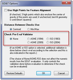 evaluate parts. When you require a standardized procedure, SA provides a full Geometric Dimensioning & Tolerancing (GD&T) package, which is available in both SA Professional and SA Ultimate packages.
SA adheres to the ASME Y14.5M-1994 standard, but also offers a wide range of flexibility. Introduced in the SA 2012.12.06 version, GD&T pre-check validations ensure full compatibility with the user’s designated standard. Supported standards include:
- ASME (1994)
- ASME (2009)
- ISO (1983)
- ISO (2004)
It is not always necessary to import a CAD model containing GD&T annotations for evaluation. SA allows you to add GD&T annotations to a CAD model and provides the tools necessary to conduct GD&T analysis on points and geometry.
SA’s GD&T module includes a wide range of capabilities. The base functionality, evaluation, and workflow can be broken into two categories. The first is GD&T design, which builds annotations and sets up an inspection. The second is the inspection itself, which walks you through the measurement process.
GD&T Annotation Design
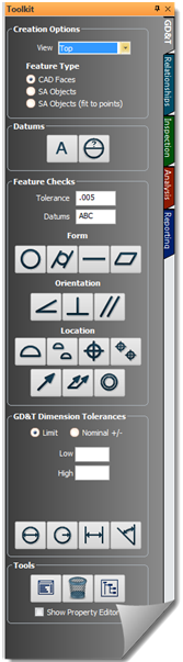
The GD&T toolbar located in the SA Toolkit is the starting point for building annotations and setting up GD&T evaluations of a part. First, select a view orientation for the annotation, and then choose the object to which the annotation will be attached (such as a CAD Face, an SA Object, or specific points). Datums and datum targets can then be added to the model and are incremented automatically.
To create a GD&T Feature Check, start by first specifying the Tolerance and Datum references used for the specific feature check. The feature check of choice can then be added by selecting the desired check from the toolbar and then graphically selecting the objects you wish to evaluate in the graphical view.
Creating a GD&T Dimension Tolerance is a similar process. Specify the dimension format first: Limit, such as 19.75-20.25, or Nominal +/-, such as 20 ± 0.25. Then click on the appropriate dimensioning symbol and graphically select the objects you wish to dimension in the graphical view.
At the bottom of the dialog, you will find a section of tools that locate, edit, or delete an annotation. Rather than searching for an annotation in the tree, simply select the desired action and then graphically select the annotation you wish to edit.
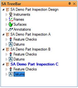
In the TreeBar, you will find that all annotations by default are contained within an Annotations category. Often it is useful to organize the design CAD and Annotations within a single collection. You can then create a new collection for a particular inspection, right-click on the Annotations category, and select “Make Feature Checks.” This will generate two additional categories: Feature Checks and Datums, which are essentially bins within which measurements of a particular feature are contained. Datums and Feature Checks behave much like relationships and need to have associated points.
Since multiple parts will often be evaluated, keeping the feature checks and datum measurements for each part in separate collections is an easy way to keep track of individual parts within a job file. The annotations and nominals do not typically change, so only a single set of annotations need to be maintained with the part.
Classical GD&T Design, Rehearsal, and Inspection 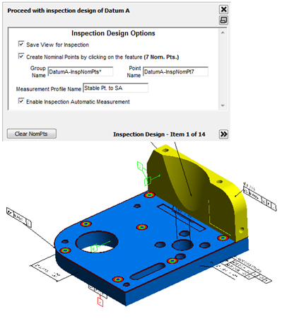
Not only does SA provide the option to build the annotation for an inspection, but it also enables the inspection designer to lay out exactly how and where to measure the part. By right-clicking on the collection containing the feature checks, you can select Inspection>Design which will walk you through the process of laying out inspection points on a part using a specific view. It will also allow specification of Group and Target names for each point measured, and provide an option to set the measurement profile and start the measurement process automatically. Each of these properties can be set individually for each datum and feature check conducted.
Once a GD&T evaluation has been designed, you can right-click on the collection and select Inspection>Rehearse. This option allows you to walk through the inspection process in simulation using mouse clicks for measurements to simulate the complete GD&T analysis conducted by the operator.
When you are ready to carry out a part inspection, right-click on the collection and select Inspection>Inspect to start the inspection process. SA will walk you through the inspection laid out by the designer and allow you to measure the part as specified. As measurements are taken, they will be associated with the appropriate feature in the tree and an analysis will be carried out automatically. This can be as easy as measuring the point on the part designated by the bullseye on the nominal CAD part.
Optional Variations for Accelerated GD&T Evaluation 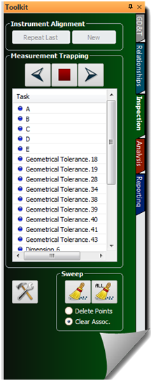
Classical Design and Inspection routines are intended to separate the GD&T design phase from the inspection or operation phase. In addition to these capabilities, SA provides a number of tools for more advanced GD&T applications.
First, the design phase can be skipped entirely if necessary. As soon as Annotations are available, Feature Checks and Datums can be built. By simply trapping measurements to each of the Datums and Feature Checks, you can associate points directly, as if you were trapping points to a relationship (the only difference here is that you have to decide where to take the measurements). Both the Datums and the Feature Checks show up in the Inspection tab of the SA Toolkit, making it easy to progress through the features.
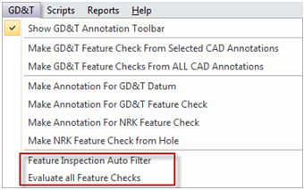
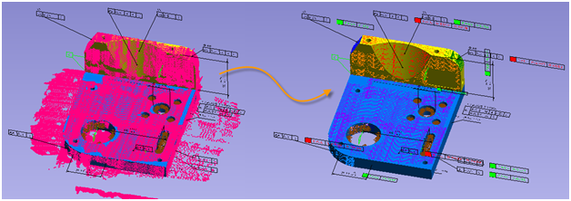
Taking this concept a step further, you can potentially measure all the features on the part independent of the GD&T analysis process, then come back after the fact and associate the appropriate measurements with the corresponding Datums and Feature Checks. SA provides two highly efficient options in GD&T for this type of analysis. Once you have measured your part, you can go to the GD&T menu and select Feature Inspection Auto Filter. This filter goes through all the measurements in the job within a specified distance from the part (whether they are individual points, point groups, or point clouds), filters them into individual groups associated with the particular CAD face, and assigns them to the appropriate feature check or datum in one operation. Of course, this method requires CAD surfaces and an initial alignment needs to be performed to get the points close to the appropriate surfaces. Afterwards, the Evaluate all Feature Checks option will complete the GD&T analysis.
This is a particularly useful approach to GD&T when using a scanner. If you initially locate a scanner and then fully scan the part you are evaluating, you are just two clicks away from a completed GD&T analysis.
GD&T Reporting 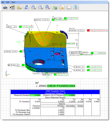
Once feature checks have been evaluated, the number of points used and the PASS/FAIL status is displayed in the tree. These feature checks can be easily added to a report by using drag and drop. Alternatively, you can generate a composite report of all the feature checks by right-clicking on the Feature Check category and selecting Composite Quick Report>Generate. This will automatically generate a report containing a snapshot of the part in the saved view used for the measurement and the resulting success or failure of the check. By right-clicking on the check, you can either add a summary table (which shows more detail on the overall residuals), or a details view (which shows the point coordinates and offsets for each point used in the analysis).
Need more help with GD&T? NRK offers regular training classes and custom training options, click here to learn more.
Questions? Contact NRK at support@kinematics.com.
Sign up to receive our eNewsletter and other product updates by clicking here.