SpatialAnalyzer & Laser Trackers at Lockheed Martin
 Determinate Assembly (DA) is a technique used in aerospace assemblies that requires drilling precise and matching hole patterns for fastening mating parts. The DA technique is critical to building large structures effectively for aerospace as it allows for consistent, accurate assembly and component alignment. Massive NC machines or large jigs are often used in order to achieve the necessary precision to drill DA hole patterns, but these methods are both expensive and inflexible to changes in design and process. An alternate technique employs a robot on a rail using a large scale precision metrology system. This technique allows DA hole patterns to be drilled precisely in a cell capable of adjusting to changes in design and process.
SpatialAnalyzer & Laser Trackers at Lockheed Martin
As metrology hardware has become increasingly more accurate over the years, the advancements in metrology software have increased in terms of accuracy and efficiency as well. A significant advancement is the ability to use a laser tracker to measure the angle normal to a mirrored surface (prior to this advancement, theodolites were typically autocollimated to measure the angle normal to a mirrored surface). This can be accomplished by measuring a stationary SMR through the mirror, and then measuring the SMR directly. The question then becomes, what is the accuracy of such a technique?
Bob Elliott at Lockheed Martin undertook this study, along with the help of SpatialAnalyzer® (SA), to observe and document the effect of distance and angle of incidence when measuring mirrored surfaces with a laser tracker. To accomplish this study, two sets of measurements were taken and analyzed:
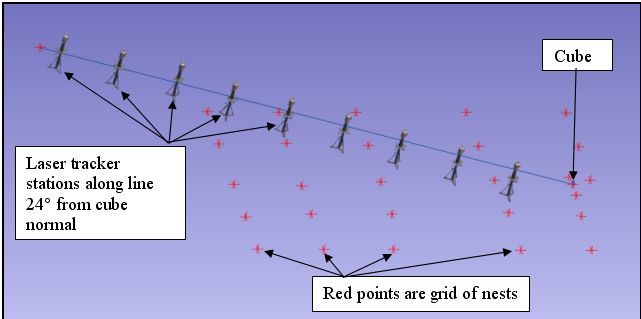
- The distance between the laser tracker and the mirrored surface. To find this, a fixed cube on a stable surface with SMR nests distributed around it was measured at fixed distances along a line at 10’ intervals.
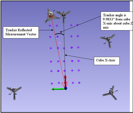
- The angle of incidence of the laser beam to the mirrored surface. For this set of data, the tracker was stationary and the cube was set on a rotary stage and rotated 10 degrees for each measurement set. Theodolite measurements were taken in addition to tracker measurements for comparison in accuracy.
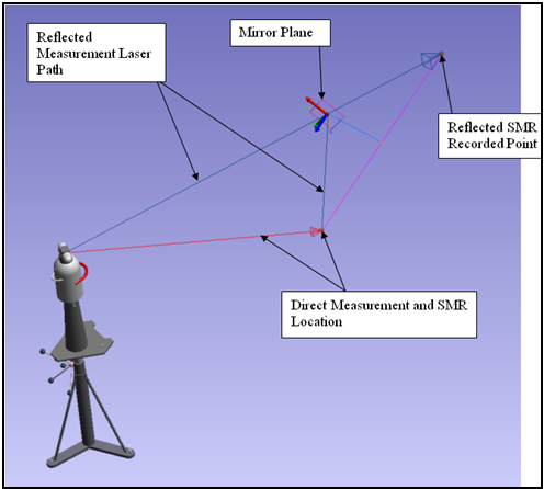
Measuring a mirror surface with a laser tracker can be accomplished by measuring two points. First, the laser beam of a tracker is reflected off the surface of the mirror that is being measured, and an SMR mounted on a stable stand collimates the reflected laser beam. Next, the SMR is rotated in order to be measured directly by the laser tracker. Using these two measurements, SA (using “Construct/Planes/ Mirror from 2 Measured Points”) can calculate the vector normal to the mirror and the position of the mirror plane.
The Distance & Angle Tests
To accomplish both the distance and angle tests, Elliott used several different SA capabilities. Unified Spatial Metrology Network (USMN) was used to optimize the uncertainty of the grid measurements taken with a Leica 901 laser tracker. With multiple theodolites composing a 3D theodolite system, SA was also used to measure points on the cube and the drift nests. From there, uncertainty fields were created and the measurements from both the trackers and the theodolites were optimized using USMN’s Point Groups command. Elliott also used SA to establish a “shoot line,” which was a line centered on the cube, extending to the corner of the room at an approximately 24 degree angle.
The most significant SA capability used in this process was USMN, which allowed Elliott to network data from the tracker and the theodolites into one optimized network. This feature of SA is significant because it was important to accurately relate the angle of the mirror cube to the grid of drift nests. The nests and cube were measured at each tracker position and the data was combined with the initial survey using USMN in SA. This method of analysis yielded cube angles at each station in a common coordinate system. The ability to use laser trackers and a 3D theodolite system in SA and network the data they collected to optimize the uncertainty is a unique feature of SA that made this project possible.
Questions? Contact NRK Support at support@kinematics.com.
Sign up to receive our eNewsletter and other product updates by clicking here.