Installing Off-Shore Oil Platforms with SpatialAnalyzer
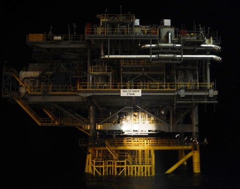
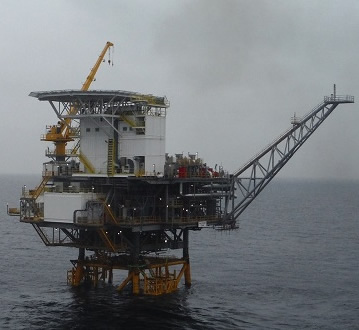
 There are approximately 850 operational offshore oil rigs, or oil platforms around the world. These multipurpose structures support the process of well drilling, the extraction of either oil or natural gas, and the processing and storing of the product until it is transported to shore for refining and use. Many oil platforms contain extensive housing and transportation facilities for staff as well.
 Installing Off-Shore Oil Platforms with SpatialAnalyzer
There are approximately 850 operational offshore oil rigs, or oil platforms around the world. 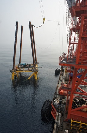 These multipurpose structures support the process of well drilling, the extraction of either oil or natural gas, and the processing and storing of the product until it is transported to shore for refining and use. Many oil platforms contain extensive housing and transportation facilities for staff as well.
Depending on the type of oil platform and the environment, the structure may float or be fixed to the sea floor. In either case, the oil rig structure is typically assembled off site and must be installed on top of the anchoring structure at sea.
Accurate measurement is essential for a successful installation at sea. Read on to learn how SpatialAnalyzer® (SA) makes this possible.
The Job:
Engineer Sam Jarvis was tasked with the installation of an oil platform deck onto steel legs anchored directly into the seabed. This particular platform supports an enormous load with deck space sufficient to support drilling rigs, production facilities, and housing quarters.
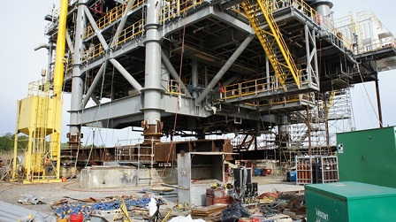
The challenge was to accurately measure these steel legs and determine the correct cut-off height to perfectly match the deck structure while at sea.
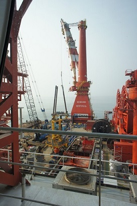
The driving dimensions for selecting the cut elevation came from the four vertical pipes on the top deck (the dimensions were fixed in the fabrication yard on shore).
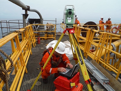
Using a total station to survey the position of the pilings relative to sea level, the engineers were then able to use SA to determine the optimum cut-off height and then drive the total station laser to mark the piles for accurate cutting. See below for the details of the job.
The Details:
- The first step in the process was to establish the position and orientation of each of the steel support legs. The pilings were rusty, so to ensure that the total station recorded good data, white lines were painted on smooth sections of the surface in areas without welds. These white marked sections were then surveyed at approximately 30 points using reflector-less targeting mode from a shipboard location.
- In SA, a cylinder was then fit to each data set and a center line established for each cylinder representing a steel leg.
- A cut plane was then added in SA and set at the nominal design height above sea level, and a point was created at the intersection of each cylinder axis line and the plane.
- Next, an optimization process was started. Since the exact location of the deck piles were known and fixed, the cut location of the steel legs had to be adjusted by moving the cut plane vertically up and down the cylinders to optimally match these distances.
- The point to point distances between each center point were obtained and then the plane was moved up or down to shrink the span distances. Once the best distance chart was agreed upon by all, the layout design was finalized.
- In SA, the cylinders and the plane were converted to bounded surface objects.
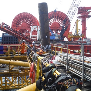
- A B-Spline was created at the intersection of each of the two surfaces (cylinder surface and plane surface) for all four legs. SA was then used to layout 30 points along the B-Spline that related to each leg cut plane.
- Assessment of which points would be visible from the scope position was made and points hidden from view were deleted from the project.
- The total station was put back on the tripod and then SA was used to point to each target that defined a cut plane point on the steel legs. One by one, the center punch was guided onto the mark and “pop” marked with paint.
Total Time:
The time from set-up to final “pop” mark was about two hours. The set-up and data collection on the day of the installation took about 40 minutes, the office calculation took approximately 40 minutes, and the final set out of marks took another 40 minutes. The final installation proved the accuracy of the measurements when the platform fit within a millimeter of dead center.
Sign up to receive our eNewsletter and other product updates by clicking here.