Relationships in SA - Part 2
 One of the most powerful tools in SA is relationships. SA enables users to utilize relationships between graphical objects, CAD models, and points to effectively align measurements from an as-built part to its nominal geometry. In our previous newsletter, we gave a basic overview of relationships in SA and reviewed some of the ways relationships can help you move objects in powerful ways to minimize error and compare ideal models to measured results. Recent developments in SA relationships offer dynamic new capability— primarily focusing on increasing automation and providing continual feedback to the user during the measurement process.
 Relationships in SA - Part 2
Getting the Most from Relationships in SA
One of the most powerful tools in SA is relationships. SA enables users to utilize 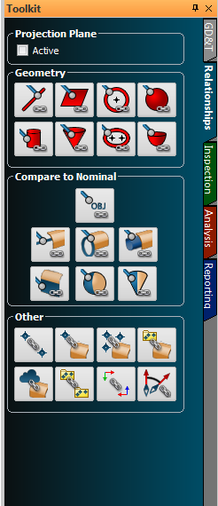 relationships between graphical objects, CAD models, and points to effectively align measurements from an as-built part to its nominal geometry. In our previous newsletter, we gave a basic overview of relationships in SA and reviewed some of the ways relationships can help you move objects in powerful ways to minimize error and compare ideal models to measured results. Recent developments in SA relationships offer dynamic new capability— primarily focusing on increasing automation and providing continual feedback to the user during the measurement process.
Geometry Relationships
With the addition of the SA Toolkit in the SA 2012.07.09 version, building and utilizing relationships are just a single-click away. Two primary types of geometry relationships are easily accessible through the new SA Toolkit:
• Fit & Compare to Nominal
• Fit only
The relationships listed above are different from simple points-to-points or points-to-object relationships. Geometry relationships utilize the measurements to build and/or compare directly to geometry and the geometry is updated with every point that is added or removed from the relationship.
For example, in order to measure a hole in a part without a CAD model, you may want to visualize the cylinder of the hole you’re measuring and see how each additional measurement impacts the overall cylindrical fit. To accomplish this, define a cylindrical geometry-relationship by simply adding one to your job file via the SA Toolkit (this is also available through the Relationships menu in the Main Toolbar). You can build this relationship prior to measuring the hole. When you do this, both a relationship and a grayed out “GR-cylinder” (for Geometry Relationship) will be placed in the tree. To associate points to this relationship, you can Trap to it by simply right-clicking on the relationship and selecting “Trap Measurements from an Instrument” to activate the relationship. You can then take measurements and each new point measured will be used in first constructing and then updating the fit of the cylinder. Any change to any of the points in the relationship fit will automatically update the size, position, and orientation of the cylinder.
The inspection tab of the SA Toolkit provides an easy way in which to trap measurements to and progress smoothly through a list of relationships. GD&T feature checks can also easily have measurements trapped to them using the inspection tab. This inspection process provides a seamless way in which to add measurements to an inspection routine which can be built prior to beginning the measurement process and can be repeated with as many parts as desired. To do so, the point associations with a relationship can be removed (without deleting the points if desired), the last instrument alignment can be repeated and the measurement process can begin again from the beginning.
Point Lists & Graphical Windows
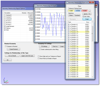 Point lists were also added to Geometry Relationships in the SA 2012.12.06 version. These point lists provide an easy way in which to determine exactly what points are included in a particular relationship. To access the point list for a relationship, simply right-click on the relationship and go to its properties. There you will find a button to access both the point list and a graph of the point fit properties for the relationship. This point list not only allows you to see which points are included but also allows you to sort them, establish a fit tolerance, and remove points that exceed this tolerance. Similar to the point list available in geometry contraction, you can now sort and remove points from a relationship with the added bonus of it being a dynamic and continually updating process. Both the point list and point graph windows are modular and can be left open while measuring. This allows you to use the graph for continual feedback regarding how each point impacts the overall fit of the geometry. If a point is out of tolerance, it can easily be found in the point list and removed from the fit.
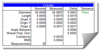
Using a Fit and Compare to Nominal relationship allows you to add an additional level of calculation. For example, if you want to check the curvature of a part and compare it to the nominal CAD surface, you can simply click on the “Cylinder from CAD” button in the Compare to Nominal section of the SA Toolkit and select the CAD surface.
Doing so will do three things:
• Define a “Cylinder from CAD” relationship that is added to the tree,
• Build the nominal cylinder defined by the CAD model,
• Build a greyed out “GR-cylinder” and begin trapping to it so that you are ready to measure it.
As you begin measuring the part, the measurements trapped to the GR cylinder will continually update it and update a comparison between the nominal and actual cylinders. This geometry comparison can be very helpful during measurement and reporting processes.
Compound Relationships for Automation
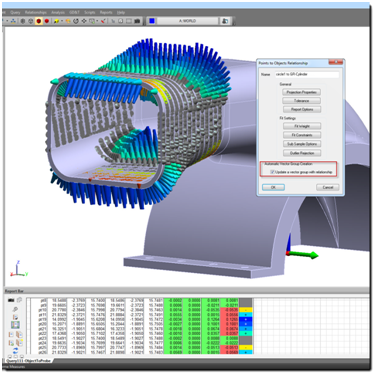
Compounding or daisy chaining relationships together can automate and enhance workflows. Relationship users are most likely familiar with the automatic Vector Group Creation function of a points-to-object relationship, which can be found by going to the properties of this type of relationship. Using this function produces a new vector with each point measured to a relationship and updates the entire vector group as any changes to either the points or associated objects are made. These vectors can be extremely helpful in determining how well measurements have been aligned with a nominal part or for visualizing deviations between a nominal and actual part. But did you know that you can build a points-to-objects relationship with an auto vector group between a group to be measured and geometry defined by a geometry relationship? Doing so allows you to visualize the relative distance between a point and an object, as well as the impact that measurement made to the relative position and orientation of the object being fit.
Continuing on methods of tying relationships together, you can also tie multiple geometry relationships together. Since adding a geometry relationship to a job adds both the relationship and the default geometry prior to measuring, a second relationship can be built using the point group that defines the first relationship, or that geometry’s cardinal points. If you wish to create the central axis of a hole in a CAD part that you haven’t yet measured, you can set up your relationships so that the axis is calculated for you and adjusted with each new measurement of the hole. This allows you to build relationships upon relationships, in as many layers as needed. If circular references are defined such that there is an infinite solution, then an error message will warn the user. In this way, relationships can be used to automate geometry construction prior to beginning the measurement process and can be very useful in automatically generating points used for watch windows and feature alignment.
Questions? Do you have any hints or tips of your own that you’d like to share? Contact NRK at support@kinematics.com.
Sign up to receive our eNewsletter and other product updates by clicking here.