SA Toolkit Enhancements for Streamlined Inspection
 Inspection in SpatialAnalyzer (SA) has never been easier. The newly enhanced SA Toolkit streamlines the process of repetitive inspection tasks—just add each feature needing inspection to a list of tasks and repeat the inspection as needed. The SA Toolkit provides easy access to geometry relationships as well as a structure in which to put them to use, thus revolutionizing the part inspection workflow process in SA. Below are a few of the unique capabilities recently added to the SA Toolkit.
 SA Toolkit Enhancements for Streamlined Inspection
Inspection in SpatialAnalyzer (SA) has never been easier. The newly enhanced SA Toolkit streamlines the process of repetitive inspection tasks—just add each feature needing inspection to a list of tasks and repeat the inspection as needed. The SA Toolkit provides easy access to geometry relationships as well as a structure in which to put them to use, thus revolutionizing the part inspection workflow process in SA. Below are a few of the unique capabilities recently added to the SA Toolkit.
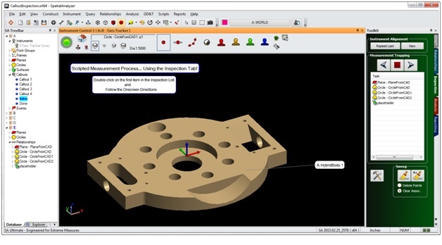
Streamlined Advancement and Navigation through the Inspection Task—
Using Repeat, Measurement Counts, and Loop & Iterate
In order for an inspection process to run efficiently, you need the freedom to measure without returning to the computer. Below are three simple ways the SA Toolkit allows you to do just that:
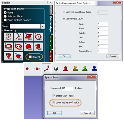
- Repeat Check Box– This check box allows you to add new features of the same type each time the Iterate button is pressed (using either one of the defined buttons on the probe or with the F7 key). For example, it is often helpful to be able to measure a series of planes or circles in sequence, one after another. By selecting this check box, a new feature of the same type will be added automatically every time the Iterate button is pressed. This allows you to measure as many points on each feature as you wish and move to the next feature with a single click.
- Measurement Counts – Measurement Counts provide the ability to define in advance how many points are needed for any particular feature. A default count can be defined and enabled for all geometry types in the user’s options, or any individual feature can be defined and applied to all like geometries directly through its properties. This can greatly increase the speed of inspection because once defined, the SA Toolkit automatically iterates to the next feature once the current feature is complete. Don’t forget to take advantage of single point circles with measurement counts turned on—this can quickly give you an accurate estimate of a hole’s diameter with a single measurement, if you have a projection plane defined.
- Loop & Iterate – On the other hand, it is often helpful to be able to simply scan a feature and have SA automatically move to the next feature when you are ready. One way to accomplish this is to return to a starting point. For example, this can be used if you wish to scan around a circle and have it automatically detect when you have completed the loop and iterate to the next feature. Alternatively, you can scan out and back to the starting point on an arc, line, or surface. This check box can be found in the right-click controls for Spatial Scan in the tracker toolbar.

Building a Guided Inspection using Callouts linked to Trapping and Enhanced Highlighting and Reordering of Features
A second major advantage to using the SA Toolkit: when measuring a part, you are also building a repeatable inspection process that can be either directly repeated or greatly enhanced to provide a guided inspection routine. Two significant enhancements have been recently made to assist in this process:
- Enhanced Inspection Highlighting – Compare to Nominal Geometry Relationships provide an efficient way of comparing a measured part to its design feature. When working with CAD, these relationships can be created by simply clicking on the CAD face of interest. It is easy to add dozens of relationships in advance to define the features you wish to measure and then begin measuring. To assist in graphically determining which feature is active, SA now highlights the nominal geometry in the graphics with an enhanced highlighting for clarity.
- Inspection Callouts – Relationships can now be directly linked to callout views so that when you initiate trapping to that particular relationship, that callout view is activated. This is in addition to adding a callout to a pre-existing callout view. Callout views allow you to control view orientation, zooming, and object visibility and watch fit statistics update in real time on the graphics as you measure, monitoring tolerances and RMS. Inspection Callouts can either be defined by right-clicking directly on a relationship and selecting “Create Associated Inspection Callout,” or by going to the callout view directly and selecting as many relationships as you wish to be tied to that particular callout view.
- Reordering Inspection Tasks – You can now change the order of progression of the inspection tasks at any time. The position of any item in the inspection task list can be changed by either selecting it directly in the list and right-clicking on the navigation buttons, or by right-clicking on the relations directly and selecting Change Order in List (just as we have for GD&T features checks).

Using measured features for alignment through the Compare to Nominal Center Point Alignment
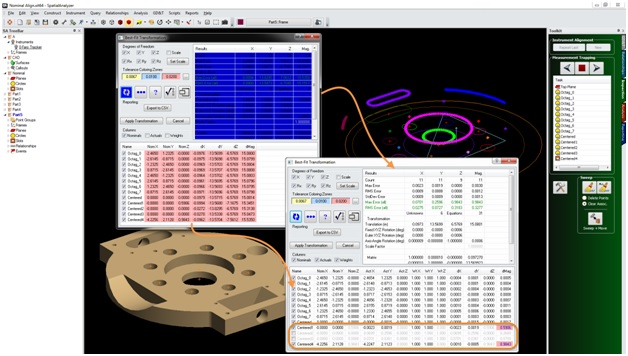
SA provides a wide selection of advanced alignment options. For a simple, straightforward alignment that allows you to take the features you have already inspected and best fit them to the nominal geometry, try the procedure below. Many features such as Spheres, Circles, Slots, Ellipses, and Average Points are point reducible and you can take advantage of this by using this new feature. To use this feature simple, follow the steps below:
- Define and measure a set of Compare to Nominal geometry relationships as you would in any part inspection process (you need at least three features to align).
- Then right-click on the instrument you wish to align and choose Locate> Nominal Geometry Relationships, and choose the relationships you wish to include in the alignment from the pre-filtered list provided for you.
- This will open a Best Fit Transform dialog that lists each relationship for you to include or exclude or weight as you wish in the fit.
When complete, the transform is applied and the instrument is snapped into position. This alignment can also be repeated through the instrument alignment button at the top of the inspection tab.

Group to Nominal Group Relationship
In the SA 2015.02.25 release, a new relationship type was added to the SA Toolkit called a Group to Nominal Group relationship. Although a group to group relationship already exists in SA, this new relationship is designed for inspection and provides the following advantages:
- As soon as a nominal group is selected, a new empty group is created and ready for inspection.
- When trapping starts, Prompter Disks or “bullseyes” are placed on each point in the nominal group to help visually guide the operator to the nominal location and help keep track of which points have and have not been measured.
- You can turn on auto-vectors and/or a closest point watch window at any time, which will guide you to the next point to measure. Trapping can be started and stopped at any time during the inspection process.
- Points are automatically renamed by proximity using the nominal group names as you measure.
Reporting Enhancements
A significant advantage of using SA geometry relationships is that every edit you make to your alignment and every point you measure automatically updates the position and orientation of the measured geometry and the comparison with the nominal. By adding those relationships to an SA Report, your report automatically updates while you measure and therefore will be complete when you take your last point. The SA 2015.02.25 release includes tools that allow you to easily select and auto-arrange sections of a report to account for dynamic table structures and reporting capabilities.
Questions about any of the shortcuts explained above? Do you have any hints or tips of your own that you’d like to share? Contact NRK at support@kinematics.com.
Sign up to receive our eNewsletter and other product updates by clicking here.