How to Simplify CAD for Metrology Jobs
 Today’s CAD models from designers have ever-increasing assembly and tooling details. The completeness of such CAD models provides a complete resource of almost every detail in the system; however, it causes the size of a typical CAD model file to drastically increase. Saving every detail in a CAD model can creates problems for measurement teams tasked with building and inspecting it. So the question is, “How does a measurement team filter a large CAD model down to only the CAD entities necessary to accomplish the job at hand?”
 How to Simplify CAD for Metrology Jobs
Today’s CAD models from designers have ever-increasing assembly and tooling details. The completeness of such CAD models provides a complete resource of almost every detail in the system; however, it causes the size of a typical CAD model file to drastically increase. Saving every detail in a CAD model can creates problems for measurement teams tasked with building and inspecting it. So the question is, “How does a measurement team filter a large CAD model down to only the CAD entities necessary to accomplish the job at hand?”
Objective:
The goal is to extract the key metrology features from massive CAD models into an organized, user-friendly structure that maintains the CAD naming and organization conventions. There are a number of capabilities in SA that enable users to quickly pare down the models so that they only include the objects needed for the job. The output is a nicely organized model that helps accelerate the measurement process and leads to cleaner analysis and more focused inspection. This creates a smaller job file and allows for more efficient communication of results from the metrology team back to designers and customers.
How:
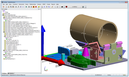
The first technique begins with importing the model with the “All CAD formats – Adobe” function. Access it with 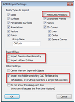 the menu, or drag and drop a CAD model/assembly into the SA graphics view.
An “Import Settings” dialog will pop after the CAD model file is selected. It has controls to select which element types are imported and which are not. For example, turning off the options for “Attributes/Metadata,” “Construction Geometry,” and “Hidden Entities” will minimize extraneous details in the SA job file.
Use the “Import into Folders matching CAD file hierarchy” option to automatically get a structure that matches the assembly component details. This step organizes all the components into folders and sub-folders that mimic assemblies and sub-components with names matching the CAD models.
There are a number of advantages to this technique that will become apparent as you begin to work with the 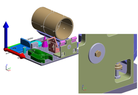 files. First, right-click and hide all the assembly folder/sub-folders, then show only the components needed for the job. The next option is to right-click in an empty region of the treeview. Select the “Select Collections to Delete” option, and then use the selection tool to quickly select the objects that are not important for measurement and analysis tasks. Using the naming convention from the CAD model makes it easier to delete individual entities (like individual screw threads, bolts, nuts, washers, and extra angle brackets, etc.). Select the Delete key and use the F2 selection dialog option “By name using wildcard”
 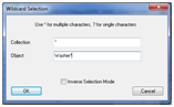 to select and delete objects with names with washer, nut, weld, screw, and bracket in them. These tasks noted above can significantly reduce the bulk and girth of unnecessary CAD entities in the job file. Analysis and file management tasks will run faster as a result.
The next CAD model simplification is a post-measurement file reduction process that will help by eliminating the bulk of non-critical metrology surfaces and faces e.g., fillets, tubing interior surfaces, weld beads, etc.
Once the objects have been measured and the instrument(s) and points are transformed, select the function Construct >> Surface >> Select faces by Projecting Points, and follow the prompts. Select all the measured points and then all the surfaces on the measured objects. This function creates a copy of surfaces that have point projections. These sets of surfaces are the ones needed for the build, assemble, and inspection processes. To reduce the model size, delete the original set of surfaces, and just keep the surfaces with point projections.
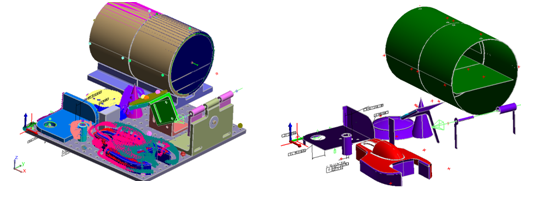
The model shown below (before and after) went from a 10.8 MB file to a 3.2 MB file after the unnecessary surfaces were deleted. The process took less than 2 minutes, plus relationship fitting and queries run faster, and the results become easier to communicate to customers.
Summary:
A consequence of increasing CAD model complexity is that metrology analysis tasks get swamped with too many non-critical surfaces. Operators are often left to figure out how to pare the dataset down too just what they need to get their job done. SA provides a series of pragmatic solutions for these challenges. Simplifying models to to their essential elements saves time and makes it easier to get the job done right.
Questions about any of the shortcuts explained above? Do you have any hints or tips of your own that you’d like to share? Contact NRK at support@kinematics.com.
Sign up to receive our eNewsletter and other product updates by clicking here.