Temperature Compensation in SA
 A noteworthy challenge in 3D metrology is accurately measuring objects that thermally expand or contract. Comparing measurements to a design part without scaling can introduce significant error, which can consume a large portion of your part tolerance and cause parts to fail that would otherwise pass inspection. To make things worse, any error in scale is cumulative, which means the error is magnified when applied to large parts. While laboratory work can be conducted at a standard temperature, real world metrology applications often take place in extreme temperatures when used to accurately assemble large metal objects that expand and contract.
 Temperature Compensation in SA
A noteworthy challenge in 3D metrology is accurately measuring objects that thermally expand or contract.  Comparing measurements to a design part without scaling can introduce significant error, which can consume a large portion of your part tolerance and cause parts to fail that would otherwise pass inspection. To make things worse, any error in scale is cumulative, which means the error is magnified when applied to large parts. While laboratory work can be conducted at a standard temperature, real world metrology applications often take place in extreme temperatures when used to accurately assemble large metal objects that expand and contract.
Once corrected, however, measurements taken at any temperature can be compared reliably to nominal CAD data, measurements of the same object at different temperatures, or components that have to be assembled. This article explains the scaling options available in SpatialAnalyzer® (SA), as well as the steps required to accurately account for part temperature changes.
How important is temperature scale on object measurement?
Just to get an idea of the relative influence of temperature on scale, let’s consider the case of an aluminum bar two meters in length. Changing the bar’s temperature by 10°C (18°F) results in a bar length change of 0.47 mm (0.019 in). This is a significant change for a metrologist, but now taking that one step further, a ten meter (32.8 ft) long aluminum object changes by approximately 0.24 mm (0.010 in) per degree Celsius due to thermal 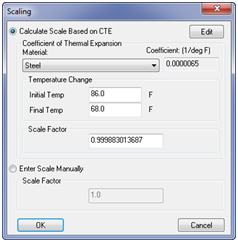 expansion/contraction. A similar steel object will change by approximately 0.12 mm (0.005 in) per degree Celsius. Therefore, as the size of the part increases or the relative part temperature difference between your measured and nominal increases, it becomes more and more important to accurately account for part temperature shifts.
While any object in SA can easily be manually scaled (Edit>Scale Objects), this is not a standard metrology approach because the resulting scaled model can only be compared to measurements taken at a particular temperature. Rather, the scale factor is typically applied as a multiplier of the instruments’ range measurements and therefore a property of a measurement station. This allows changes in temperature to be treated as additional instrument stations with scale factors for different object temperatures. By scaling the measurements to a consistent reference temperature, such as 20°C (68°F), all the stations can easily be networked together just like any combination of instrument moves. The only question that remains is the best approach to obtaining the correct scale factor for the instrument.
Coefficient of Thermal Expansion (CTE)
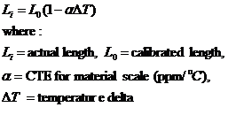
A traditional and widely accepted means of temperature compensation is to scale based on a good estimate of the object’s Coefficient of Thermal Expansion (CTE). The CTE defines how much a specific material expands or contracts due to a change in its average/core temperature. Multiplying the delta temperature by the object’s CTE will yield the amount the object should change per unit length (mm or inches) based on that temperature shift, following the basic equation:
SA can calculate the scale factor using an editable standard set of CTE values based on material type and the above equation. To set scale in SA, the average/core temperature of 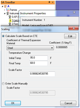 the part or tool must be measured and then that number can be used in the set scale button (Initial Temp) of the Instrument> Locate> Best-Fit dialog. Alternatively, this value can be entered by right-clicking on the instrument in the tree that took the measurements and then going to the properties of that instrument. Click on the Set Manually button and select the Calculate Scale Based on CTE radio button. You can then choose the desired material for the part and enter the initial and final temperature to establish scale. A higher initial temperature will result in a scale decrease, as it shrinks your measurements to the reference part temperature, such as 20°C (68°F),and a lower initial temperature will result in a scale increase.
For example, in the case of measuring on a hot day, you would set the initial temperature to 35°C (95°F) and the final temperature to 20°C (68°F) which will shrink the measurements of the hot, expanded part to be compared to the standard model. Once you do so, the instrument will be marked as scaled in the tree. At that point your measurements are scaled to reflect 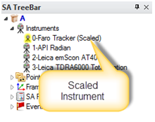 what the part/tool "should be" if it were at 20°C (68°F) (nominal temperature) and can be compared to a model built at that design temperature.
If the part/tool temperature changes during the measurement process, this can easily be accounted for by adding additional measurement stations. Optimally an alarm should be set to notify the user that the temperature has changed beyond some pre-established limit (between 2-4°C depending on the application). At that point, a new station can be added and the new Initial Temperature can be entered such that the current part/tool temperature and appropriate scale factor based on the part’s CTE is applied to the new instrument station. To set a part temperature alarm in the instrument interface, go to Devices> Part 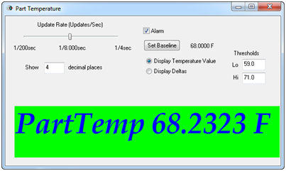 Temperature> Monitor and turn on an alarm with whatever threshold you wish.
One of the advantages of SA’s flexible architecture is that temperature scale can be adjusted before, during, or after your measurement process. Since the points are tied to the instrument that measured them, the tractability link is never lost and you can always change the scale of each instrument at any time. Remember, however, that the relative position of the points in space will change when the instrument is scaled, so scale must be applied before an alignment with other instruments is performed. If you apply a new scale factor to an instrument after an alignment, the alignment will no longer be valid.
The importance of accounting for potential sources of error-basing scale on CTE
An accurate delta temperature must be obtained in order to calculate scale based on material CTE, and therefore the core/average temperature of the object must be accurately measured to ensure good results. This is why using a certified measurement device is highly recommended. It’s also important to remember that an object’s surface temperature is not necessarily the same as its core/average temperature (surface temperatures change faster than the core). Temperature gradients across the part can easily develop, particularly in large parts, so realistic temperature soaking is often necessary for accurate measurement.
Assuming you have an accurate part temperature, you may still face challenges. Large parts may not be made from a single material type, making estimates of a CTE much more difficult. Additionally, the mounting of a part can cause pressure gradients as the constrained part tries to expand or contract (particularly in the absence of a kinematic mount).
Best-Fit Scaling (7 DOF fits)
An alternative to basing scale on CTE and part temperature estimates is the option of using the measurements themselves to establish scale. Measurements can be scaled using a network of reference points integrated into the object being measured. This practice is often called “Auto-Scaling” or “7-parameter Best Fit Transformation.” The advantage is that the scaling will change as the part expands and contracts during and between measurement jobs because of the integration of the reference network into the part. The drawback to this technique is the need to establish the network at a known temperature in a controlled environment prior to scaling.
When using SA, you can set scale base on a 7-parameter fit by simply including scale as an additional degree of 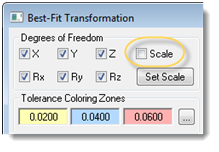 freedom in the best transformation. As opposed to using the Set Scale button available in the dialog as well, which will allow you to set the scale manually or using CTE. You can also network a group of instrument stations together and allow all of them to establish their own scale at the same time using USMN. Each instrument station can be setup to allow its scale factor to be included or set by the network optimization. Simply press the Instrument settings button and choose to include/exclude scale in the fit or apply the setting to all of the instruments at the same time.
Utilizing Like Material Scale Bars for Scale
To verify that a job has correctly controlled part temperature scaling, one option is to measure a scale bar of the same material and temperature as the part. Scaling with calibrated lengths integrates a traceable artifact into the measurement process, which adds additional confidence to the measurement scale used and can be used to directly establish scale. It’s most effective to scale based on scale bars of the same material as the material of the part being measured, and to ensure that the nominal scale bar temperature matches the nominal (modeled) CAD temperature of the part. The length of the bar should also be close to the diagonal length of the object for best results. If the measured length of the bar is very close (usually .002 in) to the calibration sticker on the bar, success is declared.
Several scaling challenges can be overcome through the use of like material scale bars. For example, adding multiple bar positions enables you to set different scales at different locations on the measured object. When measured into different groups by different instrument stations, a solution for a local scale factor can be found which will allow a consistent method to adjust for thermal gradients. In a stable environment such as a tall building with warmer temperatures near the ceiling, this can be quite helpful. The same can be said for different calibrated scale bar materials. When surveyed by additional instrument stations, the same method can be used to compensate for different CTEs within the same surveyed part.
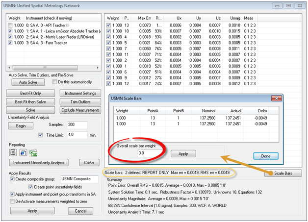
Scale lengths with uncertainty estimates can also be effectively considered as instruments within a network, making scale bars an extremely useful tool when performing a USMN analysis. The point-to-point residuals between observations and the calibrated distance can be added as corrections to the network during the optimization. When weighted with their published uncertainty statement, they constrain the resulting Composite Point Group with appropriate weights.
The USMN solution integrates scale lengths as either “Report Only” or as “Constraints” in its optimization and target uncertainty analysis processes. As “Report Only,” the scale bar does not add corrections to the network, but instead provides a reality check for your scaling procedure providing a maximum error and RMS value. When the USMN solution uses scale length as “Constraints,” the network is adjusted along with the components to minimize the delta between the length inputs. This method adds physical traceable length(s) to the network. Reports and instrument uncertainty analysis include direct comparison against these traceable standards.
While instruments automatically adjust their measurements to account for changes in air temperature, pressure, and humidity, thus providing the most accurate distance measurements possible of the part, the user must account for part temperature scaling resulting from thermal expansion and contraction. A challenge for users is to reliably scale those measurements back to a reference temperature to allow accurate evaluation of the part in comparison with its design state. While all scaling procedures require careful consideration, SA offers multiple options to accomplish this with ease and accuracy.
Questions? Contact NRK Support at support@kinematics.com.
Sign up to receive our eNewsletter and other product updates by clicking here.