Understanding & Troubleshooting GD&T Alignments
 Learning to effectively utilize and troubleshoot GD&T analysis can be a saving grace when you are faced with the question “Why did my check fail?” This article will explain the fundamental principles of GD&T evaluation, both to help clarify the expectations of the standard and provide some best practices for visualizing and/or troubleshooting your results in SA (for a more complete and authoritative review, please refer to either the ASME or ISO standard directly).
Understanding & Troubleshooting GD&T Alignments
Learning to effectively utilize and troubleshoot GD&T analysis can be a saving grace when you are faced with the question “Why did my check fail?” This article will explain the fundamental principles of GD&T evaluation, both to help clarify the expectations of the standard and provide some best practices for visualizing and/or troubleshooting your results in SA (for a more complete and authoritative review, please refer to either the ASME or ISO standard directly).
Basic Concepts in Datum Alignment
First, let’s review a few fundamental concepts. The goal of GD&T datum alignment is to define a set of key features that establish the base reference or alignment for the part (from which all other measurements taken will be relative). When a particular surface or feature is designated as a datum, the feature type is determined and the restrictions inherent in that feature type are applied to the part, helping to define its placement. A datum feature establishes either a point, a plane, or an axis and restricts the degrees of freedom controlled by that feature type.
- A spherical datum defines the XYZ position of a single point on a part. It holds that point and allows full rotation about that point.
- A planar datum functions like placing a part on a tabletop. The part is constrained to the surface but can slide and twist upon it. It cannot tip or be moved off the surface. Relative to the plane’s frame, it constrains motion in Z and rotation about Rx (u) and Ry (v) but allows freedom to move in X, Y, and rotation about Rz (w).
- An axis datum such as a hole or pin defines an axis upon which a part can slide or rotate. Relative to the axis (Z), it constrains all movement in X and Y, and rotation about Rx (u) and Ry (v) while allowing freedom of motion in Z (along the axis) and rotation about it, Rz (w).
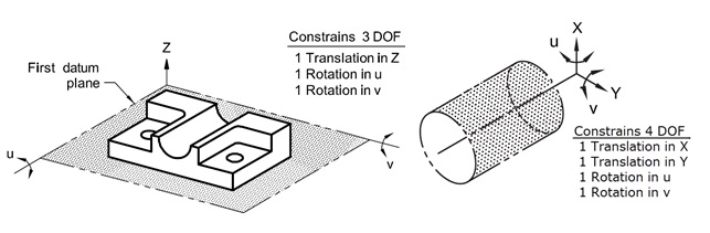
Figure 1. Planar and axis Datums showing the Degrees of Freedom controlled by each.
Although a more complicated feature can also be a datum, such as a cone or slot, these features are simply a combination of more than one of the three basic feature types combined into a single datum. For example, a cone includes both a point location like a sphere and an axis like a cylinder. It therefore locks down the degrees of freedom controlled by both added together (all three translations and two rotations). However, this more complex datum type is typically not used since it biases a single feature and does not provide the control you get from handling each aspect of the alignment independently and placing a priority on each.
Datum Priority
Datums are used in a hierarchical fashion. The degrees of freedom of the Primary datum are applied first, and then the Secondary datum is used to constrain only the remaining degrees of freedom left untouched by the primary datum, and only then is the tertiary datum considered. By definition, therefore; there will always be error in the alignment to the secondary datum if the part is not perfect, as shown below:
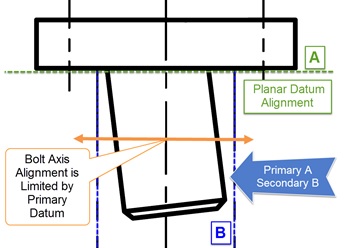
Figure 2. Datum Priority and Resulting Error in Secondary Datum when Primary Degrees of Freedom are held.
Because of this datum hierarchy, it is important to understand how the resulting error in secondary or tertiary datums is handled. The important thing to remember is that points are never compared directly to the nominal feature in GD&T. Instead, they are used to establish the measured features and then the two features are compared to each other in order to establish if the part is in tolerance. This can cause some surprising results depending upon how the primary datum actually constrains the fit. For example, if your primary datum defines an axis about which a secondary planar fit is to occur, then the measurements will be rotated to optimize the planar comparison, not the point to plane comparison. In other words, the data will be rotated such that the planes are parallel.
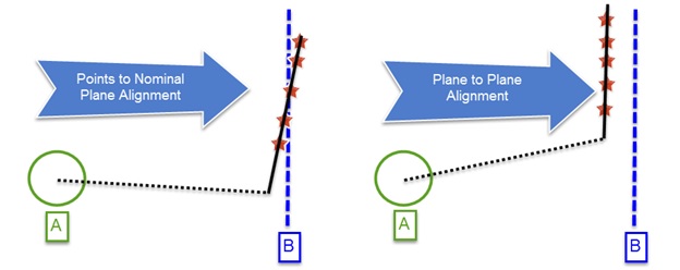
Figure 3. Object to Object Alignment in GD&T.
Understanding Datum Alignments in SA
There are a number of considerations specific to portable metrology that come into play when performing GD&T datum alignments. To start, each datum is considered independently and SA needs to correctly place the instrument and compensate for any point offsets using in calculating the datum’s position. But, when considering a single datum, there are often more ways than one to fit the data. For example, if you measured a plane, you need a way to determine if the plane was measured from above or below. There are two components used in SA for this determination:
- Probing Direction – Either Line of Sight or the 6D probe vector
- Surface Normal Direction – The positive side of the feature
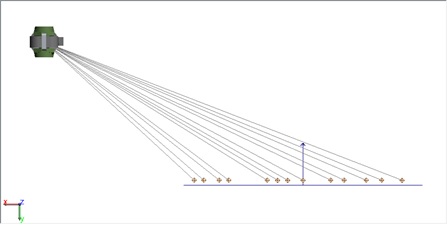
Figure 4. Instrument alignment to a plane. Offsets are applied to the positive side of the plane.
An assumption is made that when you measure a part, you cannot see through it. Therefore, Line of Sight is a reasonable assumption for determining the direction in which a feature was measured. This works for a tracker or a total station, but PCMM arms can reach around a part so a different method is needed. With 6D measurement devices, the probing vector is used to determine the approach of the instrument to the feature being measured.
Point offsets are correctly applied when you measure the positive side of a surface or object. However, there are cases where you want to measure a part “indirectly.” For example, one way to measure the bottom of a part sitting on (or attached to) a flat surface is to measure that flat surface rather than the part itself. SA provides an option to override the normal alignment process in the Datum Properties. When “Measured Indirectly” is selected, the points are compensated in the opposite direction. This shifts the part such that both the points and the part lie on the same side of the measured surface.
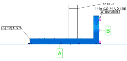
Figure 5. Datum A was measured indirectly in this part.
Aligning with GD&T Datums in SA
Another important point to understand when considering a datum Alignment in SA is that the particular alignment for each individual check is conducted on a per check basis and behind the scenes. In other words, the current alignment is not used in the feature check evaluation process.
Try the following exercise:
- Go to Help>Open Sample Files>GD&T with Multigage.xit.
- Right-click on the instrument and drag it graphically a short distance away from that CAD model so you can see that the points are not aligned with the part.
- Next, in this condition, right-click on the feature check category and evaluate all the checks.
- You will see that the checks still evaluate and still report the same values even though the measurements are no-longer aligned to the part.
This illustrates a fundamental concept of GD&T in SA: you can evaluate various feature checks without actually being aligned graphically to the features or even the CAD model. This allows SA to evaluate all of the checks in the job without changing your current alignment. However, SA does provide the ability to align using a particular datum scheme if desired. To do so, right-click on the Datums Category in the tree and choose Align, then select "Let me choose.” In this alignment dialog, you can scroll through the list of all the feature checks in the job and select any individual check datum scheme to use for the alignment. Keep in mind that if you have more than one instrument station, you will need to use the option to move additional instruments "Prompt for Additional Objects to Move.” This will ensure that you move the additional instruments along with the station that measured the datums.
Being able to visualize the alignment used and see the point deviations is often times critical, particularly if you are trying to track down a bad result and understand why. By being able to apply different GD&T alignments helps you do just that. Once aligned, you can build vectors and callouts to help illustrate any issues that are then displayed.
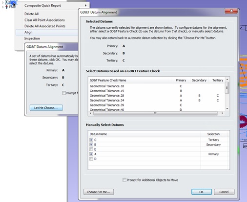
Figure 6. Aligning using a GD&T Datum scheme.
There is an example MP available on NRK’s website that will help illustrate this process. It walks you through all the checks in the job, performs an alignment, builds a corresponding vector group, and captures a picture for each feature check to illustrate the deviations. This MP can be found here:
http://www.kinematics.com/ftp/SA/Install/Examples/Functional/
Turning Off GD&T Alignments
There are times when it can be helpful to use other alignment methods such as relationship fitting in order to align to a part and evaluate features using a GD&T type evaluation. There is an option within the Feature Check properties dialog that allows you to do this. When a datum alignment is disabled for a particular check, the datums will be crossed out in the annotation because they are not used, like this:
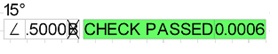
Figure 7. Disabling Datum alignment to use a manual alignment in the evaluation.
Doing so tells SA to skip the datum alignment entirely, hence the “X” through the datums. In this condition, SA is using your current instrument alignment to evaluate the check. This is no longer a “Standard-complaint” fit, but can be helpful in understanding if the GD&T alignment is returning significantly different results than an RMS based alignment would return.
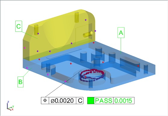
Understanding Reported Results
GD&T report tables provide more than just a Pass/Fail result. By turning on additional reporting options, you can access all the essential details about the Datum alignment and Check results.
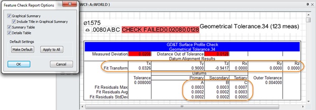
Figure 8. Feature Check Report and Summary Table.
When a Check fails, it will report two numbers (as shown in figure 8). The first number, 0.0208, is the "Measured Deviation," or the size of the tolerance zone required for the part to pass (this is a diametrical zone). The last number, 0.0128, is the "Distance out of Tolerance," or the distance you would have to move for the check to pass (or the radial distance out). Within the Summary table is a “Fit Transform” section. This tells you how far the data had to be transformed from its current location to fit the GD&T datums. If the transform is not all zeros, then this is an immediate tip that the check was not evaluated in the part’s current graphical position. The fit residuals for the datums are also reported, making it easy to see if there was a problem in fitting one of the datums. By checking to see if there was a bad fit to one of the datums or if the transform is significantly larger than you would expect, you can quickly determine if a check is failing due to a bad datum alignment rather than the features themselves.
GD&T operators are often faced with difficult questions when a part fails, and it is important to be able to deliver a clear and intelligent answer as to why the results reported are correct. The place to start when you double check your results is the datum alignment. Once you understand and have confidence in your alignment, the check results become fairly self-explanatory.
Questions? Do you have any hints or tips of your own that you’d like to share? Contact NRK at support@kinematics.com.
Click here to learn more about our custom applications or click here to read more about our applications.