The Oasis of the Seas--VSTARS & SA
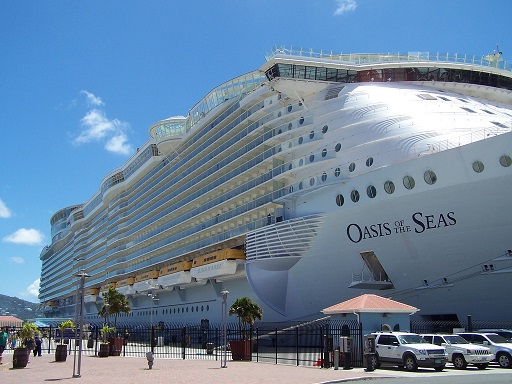
 The Oasis of the Seas is the largest passenger ship in the world with a gross tonnage of 225,282 and room for more than 5,400 passengers. Not surprisingly, it creates a huge bow wave when sailing the seas and encounters waves of over 60 feet when crossing the Atlantic Ocean. When wave action began damaging the forward pair of port and starboard lifeboats, it was decided to install wave-deflecting sponsons to protect the lifeboats. Sponsons are projections from the sides of watercraft that provide protection or stability. The metrologists at 3Space Measurement Specialists were responsible for measuring and defining the complex shape of the hull in the area just forward of the first lifeboat station so that the sponson could then be designed and fabricated.
 The Oasis of the Seas: VSTARS & SA
The Oasis of the Seas is the largest passenger ship in the world with a gross tonnage of 225,282 and room for more than 5,400 passengers. Not surprisingly, it creates a huge bow wave when sailing the seas and encounters waves of over 60 feet when crossing the Atlantic Ocean.

When wave action began damaging the forward pair of port and starboard lifeboats, it was decided to install wave-deflecting sponsons to protect the lifeboats. Sponsons are projections from the sides of watercraft that provide protection or stability. The metrologists at 3Space Measurement Specialists were responsible for measuring and defining the complex shape of the hull in the area just forward of the first lifeboat station so that the sponson could then be designed and fabricated.

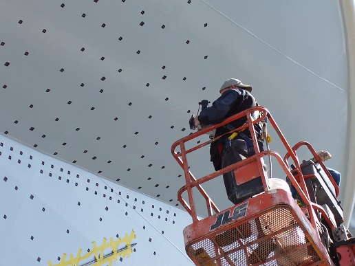
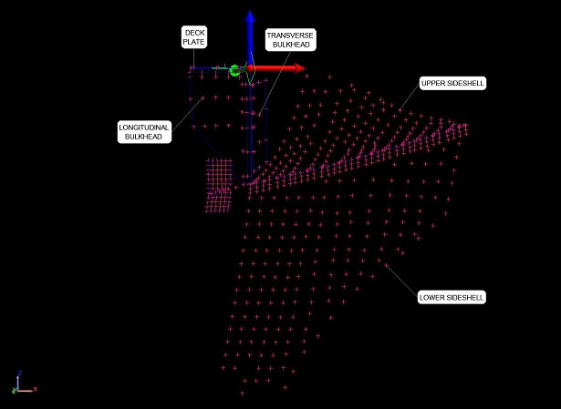
The challenges of this project were many. First, the area needing to be measured contains large surfaces with complex curvature, as well as the deck plate, longitudinal bulkheads, and transverse frames. Second, the ship would be tied to the pier during the time of measurement, so it would be in constant motion. Third, the metrology team would have a very short window of time in which to capture the data. Given the unique nature of these challenges, the team relied on the VSTARS photogrammetry system and SpatialAnalyzer (SA) to complete the project.

The metrology team had exactly eight hours to set-up, layout reference lines, target the hull, acquire the photography, check the data, and clean up the jobsite before passengers began boarding the ship. They met their goal with fifteen minutes to spare. After which, the data was processed as follows:
- Computed the photogrammetric bundle solution and scaled the data to its precise dimensions.
- Exported the data as an .xyz file and imported it to SA.
- Using the imported data, planes were constructed on the deck points, longitudinal bulkhead points, and the transverse bulkhead points. These planes were intersected to create an origin point, and the planes were again intersected to create lines between the deck and the longitudinal bulkhead, and between the transverse and longitudinal bulkheads. The planes, lines, and origin point were then used to construct a coordinate frame in the correct vessel coordinate system.
- The two large shell surfaces were intersected to create a b-spline line that would provide another boundary for the sponson design.
- The final step was to export the file in both IGES and STEP formats for delivery to the customer. All measurements and analysis were conducted on the starboard side of the ship, and the sponson design was mirrored in the CAD environment to an equivalent location on the port side.
Sign up to receive our eNewsletter and other product updates by clicking here.